Stair case study
The common issue that many practices in AEC are facing nowadays, is managing a big amount of data throughout their processes, which often are based on different platforms.
The lack of software that allows the users to empower a seamless workflow in a single environment, pushed the industry to adopt workarounds or develop bridging tools to transfer data among platforms.
The design of the step boxes for the Crown Casino Hotel feature stair presented geometrical and fabrication challenges as well as a good example of interoperability between different software.
Tools – 3dExperience, EKL, Rhino, GH
Digital fabrication — AR-MA
Videos, diagrams — AR-MA
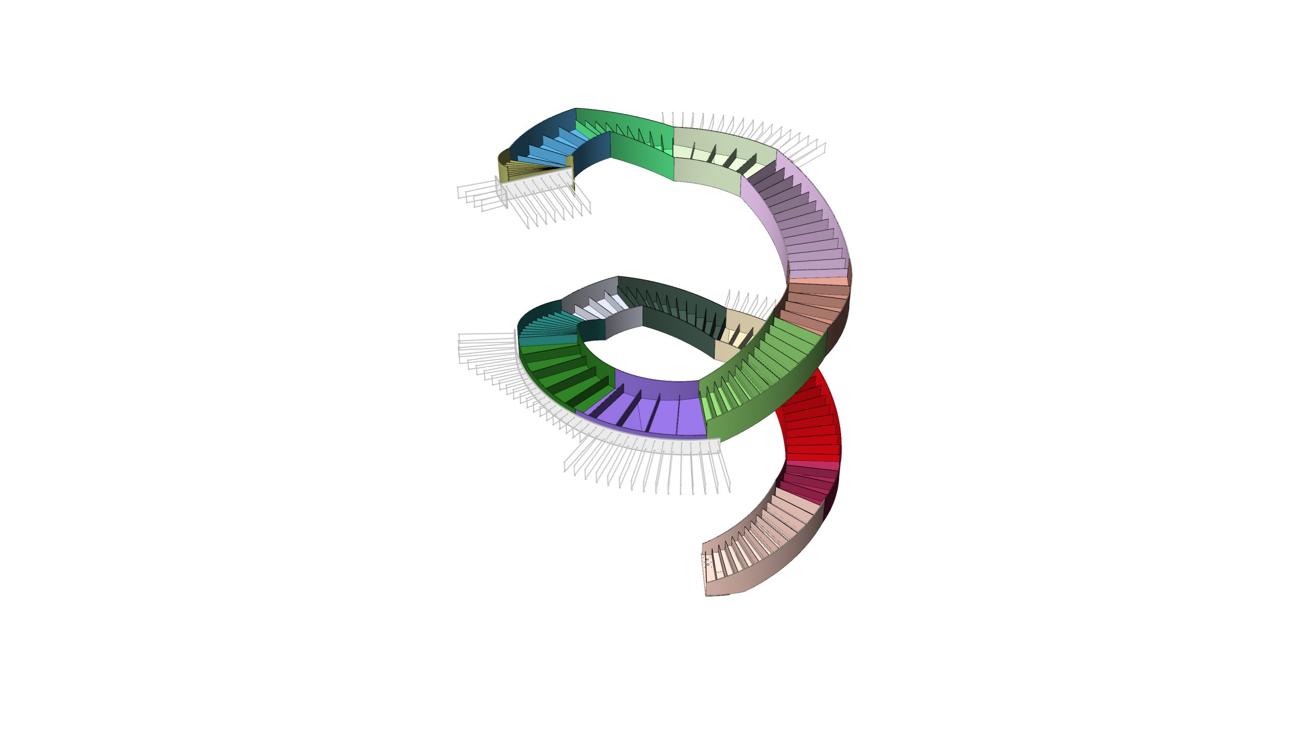
The geometry
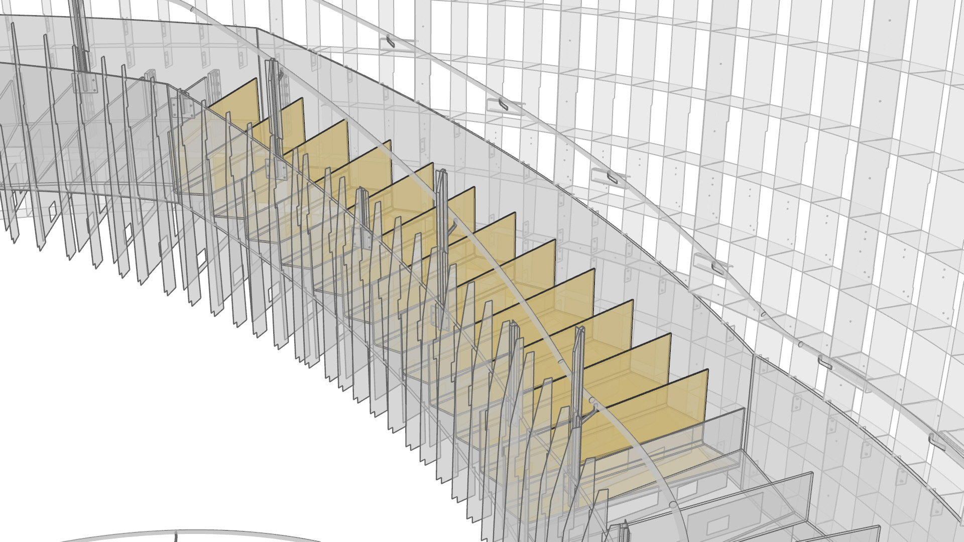
The geometry of the step box consists in a L-shape with variable angles and dimensions, driven by the location of each element between the two stringers across the length of the stair.
Furthermore, the tapered shape of the step-box is crucial for the structural integrity of the stair system, to provide support and stability for the attached elements.
To achieve the correct geometry and to manage the outcomes for manufacturing, we created a workflow based on the interoperability between Rhino and CATIA, taking advantage of the most stable SheetMetal function and the Smart Component capability of 3dxerience.
Generate skeleton in Rhino
To solve the design of the stair and to be able to manage the information.
We developed a parametric skeleton model that could reflect the design intent, the inputs from the engineers, the requests of the fabricator and provide a high level of flexibility for punctual manipulation.
On top of that, the model has been embedded with a naming scheme based on the relations between the parts for easy management of the component.
Instantiation Template
The CATIA workflow is based on a smart component: the Engineering Template and a sequence of EKL actions.
1. Organise the inputs in GeoSet
The first tool relies on the naming scheme. It detects the relations between the parts and it organises the inputs in GeoSets based on the Assemblies name.
2. Instantiate the Axis system
This tool goes through the GeoSets and instantiate the axis system that will be used to set up the drawings view and the laser cutting file for each element.
3. Instantiate the Engineer Template of the StepBox
The instantiation of the Engineering Template is the last step of this workflow and it generates the final shape of the StepBoxes using the sheetMetal component.
At this stage, we are able to modify the geometries and the output if required
When all the step Boxes are completed, we are able to update the drawings and export the fabrication outputs.
To ensure the quality of the generated 3D model and to check the correct location of each element, we import back to Rhino the step file.